


Inductors and Inductor Coils: Types, Applications and Principles
IQS Directory EditorialUpdated 6 chapters
4 leading suppliers listed with this guide
Browse induction coil suppliersContents (6 chapters)
This article will give an in-depth discussion about Inductors and Inductor Coils.
The article will bring more understanding about topics such as:
- What are Inductors and their Basic Principles?
- Types of Inductors and Inductor Coils
- Core Design of Inductor Coils
- Applications and Uses of Inductor Coils
- Inductance and Factors Affecting Inductance of an Inductor Coil
- Considerations when Choosing an Inductor Coil
- And Much More…
Chapter 1: Understanding Inductors and Their Fundamental Principles
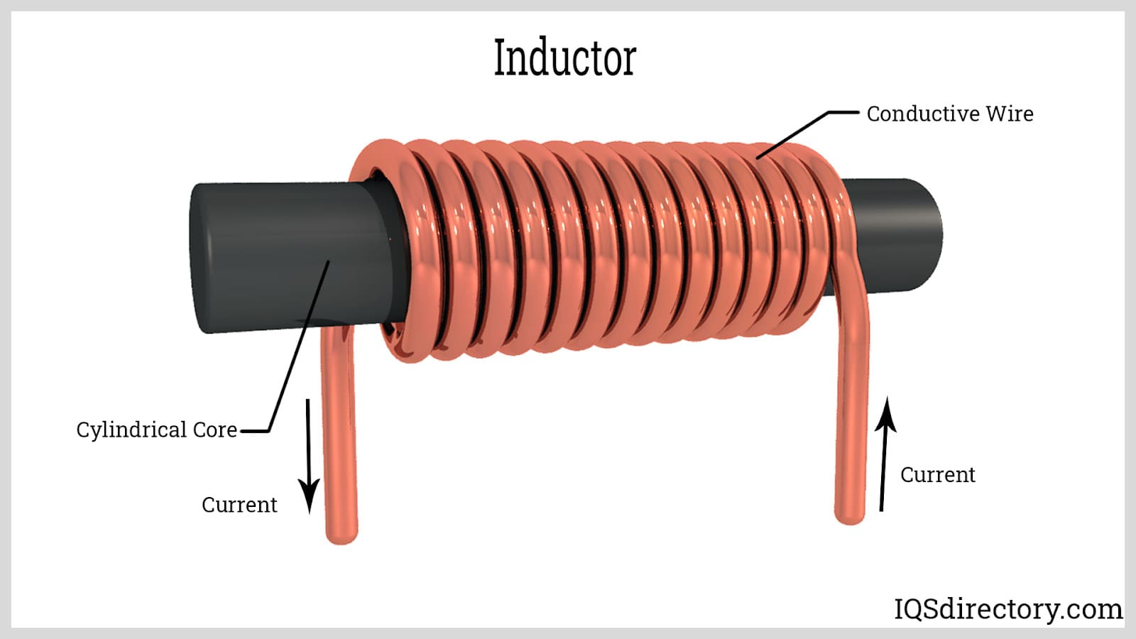
Inductors are two-terminal passive components in electrical and electronic circuits with the ability to store energy magnetically. They resist rapid changes in current and are often referred to as coils or chokes. Represented by the symbol L in electrical diagrams, inductors play a crucial role in power supplies, RF circuits, filtering applications, tuning networks, and signal processing. Engineers commonly evaluate inductance, current rating, DC resistance, saturation current, and self-resonant frequency when selecting the right component for a specific circuit design.

Defining an Inductor Coil
An inductor coil is a conductive element that facilitates the flow of electricity and induces a magnetic field. This conductor is typically wound in a coil or spiral structure, often around a ferrite core, iron core, or air core depending on the application. Common inductor types include wire-wound inductors, power inductors, RF inductors, chokes, and toroidal inductors, each designed to manage electrical energy, reduce noise, or stabilize current in electronics.
Key Principles of Inductor Coils
As electric current begins to flow through a conductive material, a magnetic field is generated in accordance with the right-hand rule. If the current passes through an inductor with coiled conductors, this magnetic field is enhanced, effectively turning the inductor into an electromagnet. In a reverse process, an existing magnetic field can also generate an electric current, which is the basis of electromagnetic induction, transformer operation, and many energy conversion systems.
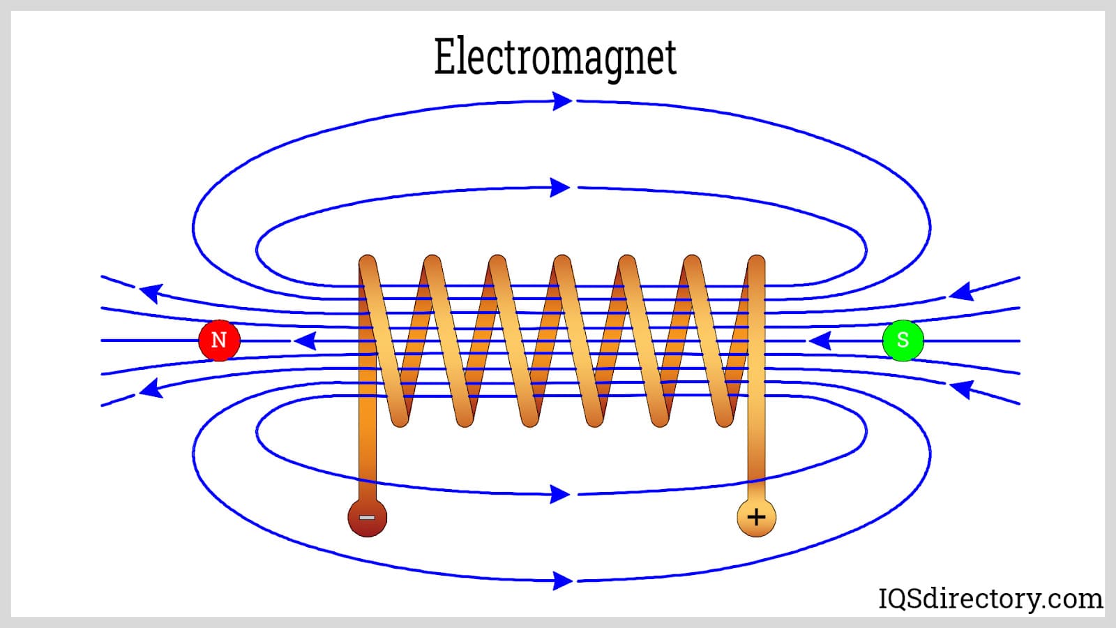
Once the inductor is magnetized, you can alter the surrounding magnetic field by moving a magnet closer or further away, which induces an electric current that operates to counteract variations in the field's direction and intensity. This phenomenon, called electromagnetic induction, is depicted in the circuit diagram below. When a DC current starts flowing through an inductor, it instantly creates an electromotive force that opposes the current's direction. This opposing voltage is also known as back EMF, and it is a key reason inductors are widely used for current smoothing, surge suppression, and filtering in electronic circuits.
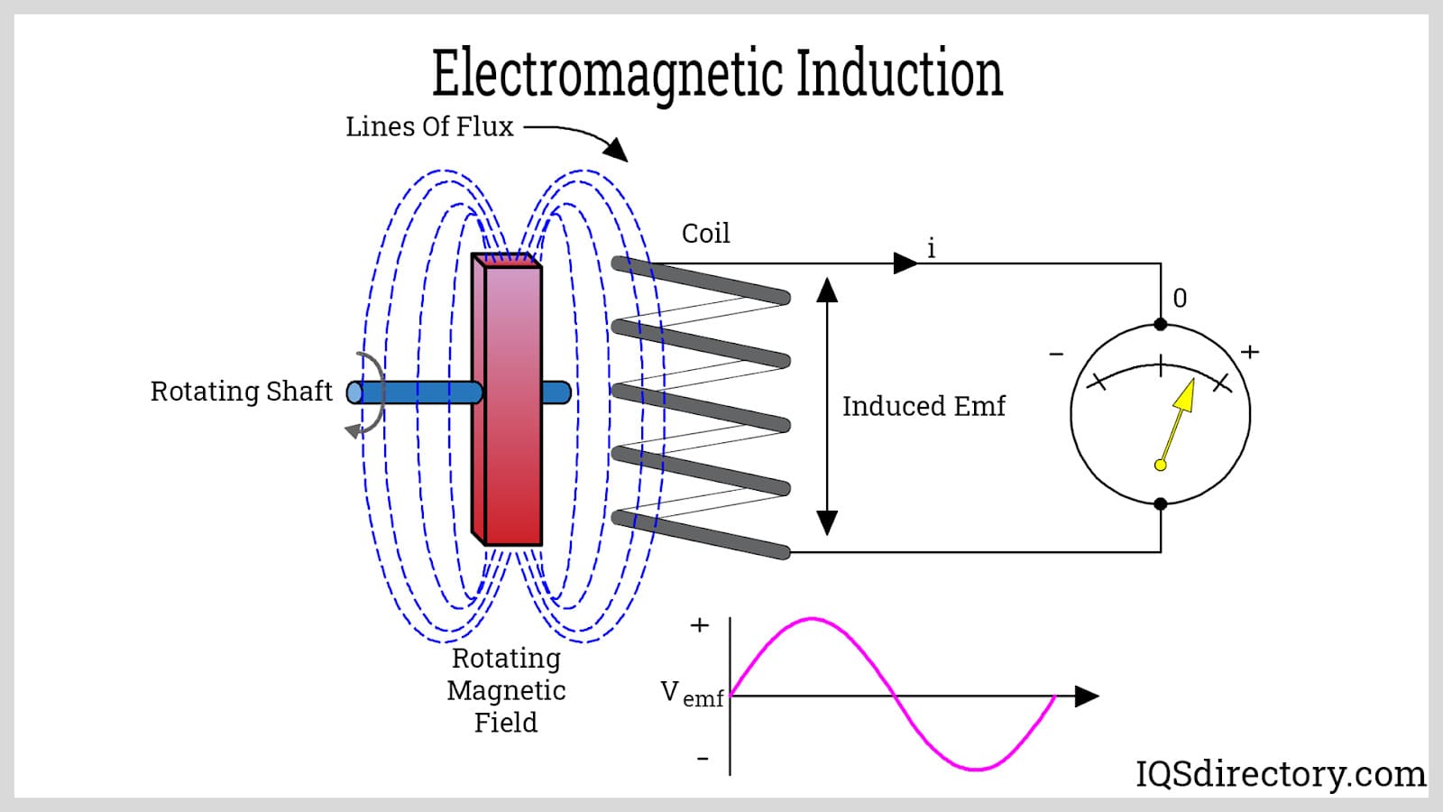
This characteristic is the self-inductive effect. However, as the DC current continues, it eventually stabilizes, leading to a consistent magnetic flux where the electromotive force dissipates, and the current essentially flows unobstructed. The electromotive force within an inductor correlates with the rate of current change (ΔI/Δt). Conversely, with AC current (illustrated below), the voltage substantially spikes when current initiates from zero due to the rapid change rate. This is why inductors are essential in AC filtering, impedance control, radio-frequency chokes, and low-pass circuits where unwanted high-frequency noise must be reduced.

As the current increase slows, the voltage lessens and hits zero once current peaks. When the current declines from its maximum, negative voltage arises, reaching a minimum as the current returns to zero. The electromotive force generates a ¼ cycle phase shift relative to voltage and current waveforms, as shown in the figure. Consequently, AC current encounters more resistance in an inductor than DC current does. If the AC current frequency surpasses a specific limit, the electromotive force continually opposes it, ultimately blocking the flow. Thus, higher-frequency AC voltages make current passage through an inductor increasingly challenging, which is why inductive reactance increases with frequency and why inductors are often chosen for frequency-selective circuits, oscillators, and electromagnetic interference suppression.
Chapter 2: What Are the Different Types of Inductors and Inductor Coils?
Inductors are essential passive electronic components that are widely used in electrical circuits to store energy in a magnetic field. These components, often referred to as electrical coils or chokes, can be categorized based on several distinct factors. Understanding the various types of inductors and inductor coils is crucial for engineers and designers when selecting the optimal inductor for power supply circuits, RF applications, signal filtering, and electromagnetic interference (EMI) suppression.
Inductors can be distinguished in three main ways. One method is based on the type of core material around which the inductor is wound. There are various types of inductor cores, including air cores or cores made from magnetic materials that enhance the inductor’s ability to store energy and determine electrical parameters such as inductance and Q factor.
Another way to distinguish inductors is by their unique characteristics, such as the shape of the coil or its physical construction. Some inductors have coils wound in circular shapes (toroidal), while others are cylindrical or solenoidal. The geometry and winding method impact parameters like distributed capacitance, self-resonant frequency, and current handling capability.
The final distinguishing feature is whether the inductor is fixed, adjustable, or variable. Adjustable inductors have a movable inner core that alters their inductance, providing flexibility for circuit tuning. If the core is made of a magnetic material (such as ferrite or iron), moving the core toward the center of the windings increases the inductance. Conversely, if the core is made of brass, moving it toward the center decreases the inductance. These variable inductors are often used in RF circuits, oscillators, antenna matching networks, and tuning filters where precise inductance adjustment is required for optimal performance.
Types of Inductor Coils Based on Their Cores
The types of inductor coils based on their core materials are detailed below, along with descriptions, construction techniques, key properties, and common applications to help guide your component selection for specific electrical and electronic projects.
Air Core Inductors
Below are the details on air core inductor construction, characteristics, and primary applications.
Air Core Construction
As the name implies, an air core inductor does not require a ferromagnetic coil form for support and is self-sustaining. It uses air as the medium for storing magnetic energy instead of relying on magnetic materials like ferrite. In certain cases, the coil can be wound in a way that allows for self-support, while in others, ceramic or insulated materials may be used for additional structure and dielectric support. Additionally, to stabilize the inductance of this type of inductor, it may be coated with varnish, epoxy, or secured with wax, helping to prevent changes due to mechanical vibration, temperature fluctuations, or moisture ingress.

Description of Air Core Inductors
Air core inductors offer several advantages due to the absence of a ferromagnetic core. These benefits include high linearity, no core saturation, and no iron losses at high frequencies, making them ideal for radio frequency (RF) circuits, wireless communication, and broadband signal processing. Constructing an air core inductor is straightforward, with stable electrical performance and minimal parasitic effects. They are unaffected by the level of electric current they carry, and their high self-resonant frequency enables operation in GHz ranges. However, the lack of a ferromagnetic core limits their L-I product, making air core inductors more suitable for low to medium power applications. High inductance values and large current handling are not feasible in compact designs with air core inductors. These are commonly used in commodity electronic products, computer motherboard circuits, Bluetooth and Wi-Fi modules, communication equipment, and other consumer goods requiring stable, high-frequency operation.
Inductor Applications and Features
- They are used in the construction of RF tuning coils, resonant circuits, and impedance matching networks
- They are integral components in filter circuits, such as bandpass, low-pass, and high-pass passive filters
- Utilized in snubber circuits for transient voltage suppression
- They are used to attain a lower peak inductance and minimize electromagnetic interference (EMI)
- They are prevalent in high-frequency devices like TVs, radio receivers, wireless antennas, and transmitters
- Applied in medical instrumentation and laboratory test and measurement equipment because of their precision
Ceramic Core Inductor
Below are details on the construction, description, and typical areas of use for ceramic core inductors.
Ceramic Core Inductor Construction
Ceramic core inductors are made from non-magnetic ceramic material, which functions similarly to air by providing a low-loss, non-reactive environment for the magnetic field. The ceramic core acts as a structural support for the conductor, ensuring precise coil shape and terminal alignment, which is especially critical in surface mount device (SMD) applications and miniature circuit designs.

Ceramic Core Inductor Description
Because it is a non-magnetic material, ceramic has very low magnetic permeability, resulting in low achievable inductance values. Core losses are minimized, and ceramic core inductors exhibit excellent stability and high Q factor, making them suitable for demanding RF front-end circuits, IF transformers, and low distortion filter networks. However, high inductance values are not practical due to the inherent material limitations.
Ceramic Core Applications and Features
Ceramic core inductors are used in applications that require low inductance levels, exceptional frequency stability, a high Q factor, and minimal core losses. Typical use cases include:
- High-frequency RF circuits in smartphones and wireless devices
- Precision filter applications and timing circuits
- Matching networks in antenna design
- Surface mount and microelectronics applications
Ferrite Core Inductors
Below are details on the construction, magnetic properties, and common applications of ferrite core inductors.
Ferrite Core Inductors Construction
These inductors are constructed by meticulously wrapping insulated copper wire around a ferrite core, which is a ceramic compound formed by mixing iron oxide (Fe2O3) with a small percentage of other metal oxides such as nickel, barium, zinc, or magnesium at high temperatures (1000–1300 degrees Celsius). Ferrite materials offer high electrical resistivity, minimizing eddy currents and heating under alternating currents. They may take toroidal, E-core, or drum shapes depending on application requirements.

Ferrite Description
Ferrite core inductors exhibit high permeability, provide efficient magnetic coupling, and experience low eddy current losses at high frequencies. Their high resistivity ensures they are well-suited for switch-mode power supplies (SMPS), EMI noise suppression, and DC-DC converters. These inductors are ideal for high-frequency applications, including filters, baluns, and chokes in telecommunications, audio/video, and computing. However, saturation losses can occur when the magnetic flux density reaches the core’s saturation point (typically 400 mT). Other disadvantages include upper frequency limitations due to increased core losses and potential temperature drift, which can cause performance shifts in tuned circuits.
Ferrite Core Applications and Features
- Used extensively for high and medium frequency switching power supplies, voltage regulators, and power electronics
- Essential in switching circuits for SMPS and LED drivers
- Employed in Pi filters, common mode chokes, and EMI/RFI suppression networks
- Frequently found in computer motherboards, digital televisions, and modems
- Employed in automotive electronics to mitigate conducted EMI
Iron Core Inductors
The construction, electrical characteristics, and applications of iron core inductors are detailed below.
Inductor Construction
As the name suggests, iron core inductors are fabricated by winding a copper or aluminum conductor around a solid or laminated iron core. The iron material serves to concentrate and amplify the magnetic field generated by the current flowing through the coil, boosting the component’s effective inductance.

Iron Core Inductor Description
Iron core inductors offer very high inductance values, thanks to the high magnetic permeability of iron. This makes them effective at storing energy in the magnetic field with fewer windings, allowing for more compact, high-current inductor designs. However, iron core inductors suffer from core losses (hysteresis and eddy current losses) at high frequencies, which limits their performance in radio frequency and high-frequency power electronics. Thus, they are best suited for low-frequency and high-current applications, such as power transformers, audio crossover networks, and electromagnetic relays.
Iron Core Inductor Applications and Features
These inductors are favored for applications where high inductance and current capacity are required while operating at low to moderate frequencies. Common uses include:
- Industrial power supplies for AC and DC power conditioning
- Audio crossover circuits in loudspeakers and audio amplifiers
- Rapid transit and railway signaling systems
- Inverter systems and battery chargers
- Power conditioning for renewable energy and backup power applications
Laminated Steel Core Inductors
Below are details on the construction, description, and primary applications of laminated steel core inductors.
Laminated Steel Core Inductor Construction
Laminated steel core inductors are manufactured using thin, insulated steel sheets, or laminations, stacked together as the core. This design is specifically intended to block eddy currents, reduce loop action, and minimize energy loss, which otherwise would increase significantly at higher frequencies due to the skin effect. Laminated cores are used when high power handling and reduced eddy current losses are needed for 50/60 Hz power line frequencies.

Laminated Steel Core Description
Laminated steel core inductors significantly reduce AC power losses by interrupting the flow of circulating currents with their segmented construction. This approach not only decreases energy dissipation but also reduces the inductor's overall weight and enables higher efficiency in power transmission and conversion.
Laminated Steel Core Application and Features
Laminated steel core inductors are primarily used in the manufacture of power transformers, large industrial reactors, and low-frequency AC chokes. Key benefits include improved power efficiency and reduced core heating in power distribution and conversion equipment.
Powdered Iron Core Inductor
Below are details on the construction, core material characteristics, and wide-ranging applications of powdered iron core inductors.
Construction of Powdered Iron Core Inductors
As the name suggests, these inductors feature cores composed of a mixture of finely powdered magnetic materials (often iron), compacted together with built-in air gaps. This unique construction allows for higher energy storage capability, superior inductance stability, and resistance to saturation, compared to standard solid iron cores. Powdered iron cores are often used for energy storage in buck, boost, and flyback converters in power electronics.

Iron Powder Core Description
Iron powder core inductors exhibit both low eddy current losses and minimal hysteresis compared to solid iron core counterparts. They are very cost-effective and provide strong inductance stability over a wide range of operating currents, which makes them ideal for switching regulators, RF chokes, EMI filtering, and pulse transformer applications. However, certain disadvantages include persistent but low core and winding losses due to the distributed air gaps, resulting in higher accumulated losses when compared to ferrite types in certain scenarios.
Iron Powder Core Applications and Features
- Utilized in low frequency DC output devices and energy storage inductors in switching power supplies
- Applied in pulse transformers, flyback converters, and power factor correction circuits
- Can withstand large AC line current without reaching magnetic saturation, ideal for inverter drives and UPS systems
- Offer inductance tolerance of +/- 10% and a high maximum flux density up to 15,000 gauss
- Used in high-efficiency EMI filters, SMPS, automotive power conversion, and industrial control equipment
Choosing the right inductor or inductor coil involves considering the application's operating frequency, required inductance value, size limitations, current carrying capacity, and the impact of core material on losses and performance. By understanding the unique features of each core type and construction method, engineers can confidently select inductive components that deliver reliable performance and efficiency in a wide range of electronic circuits and power systems.
Chapter 3: What Is the Core Design of Inductor Coils?
Inductor coils are essential electronic components widely used across industries for energy storage, filtering, and noise suppression within electrical circuits. The core design significantly impacts an inductor's performance, efficiency, and suitability for specific applications. Below, we outline the main types of inductor coils according to their core construction, electromagnetic properties, and industry-specific uses:
Bobbin-Based Inductors
Bobbin-based inductors are a popular type of passive electronic component utilized for their reliable performance in low-to-medium frequency applications. Learn more about their construction details and common use cases below.
Bobbin-Based Inductors Construction
These coil inductors are manufactured by winding insulated copper wire around a cylindrical bobbin, then enclosing it within a protective shrink tube. The core material is typically ferrite, a high-permeability magnetic material, which imparts high inductance, minimizes core losses, and enables efficient electromagnetic field generation. Like other ferrite core inductors, this structure ensures stable performance over varying frequencies and temperatures, making them ideal for many demanding power electronics applications.

Bobbin-Based Inductors Description
These compact inductors are available in miniature sizes, making them an excellent fit for space-saving circuit designs, such as modern power adapters, consumer electronics, and small-scale DC-DC converters. Their low-profile form factor and reliable electrical characteristics make them a preferred choice for high-density PCB layouts.
Bobbin-Based Inductors Applications and Features
- Widely used in SMPS (Switch Mode Power Supply) circuits for energy storage and voltage regulation
- Integral components of both input and output EMI/RFI filters
- Common in Pi filters for noise suppression and waveform conditioning
- Available in vertical mounting formats for ease of PCB assembly
- Offer industry-standard +/- 10% primary inductance tolerance
- Feature strong dielectric strength of 0.5 KV between coil and core for enhanced safety and reliability
If you're seeking an inductor to minimize electromagnetic interference, improve power integrity, or comply with EMI standards, bobbin-based inductors deliver consistent results in a broad range of consumer, industrial, and automotive electronics.
Toroidal-Core Inductors
Toroidal core inductors represent another crucial class of inductive components, noted for their unique geometry and exceptional magnetic efficiency. Explore their construction, core properties, and high-performance applications:
Toroid-Core Inductors Construction
Toroidal inductors are engineered by meticulously winding copper wire around a toroidal (doughnut-shaped) core, usually made from high-quality ferrite or powdered iron materials. This closed magnetic path core design concentrates the magnetic flux, significantly reducing electromagnetic interference (EMI) and stray magnetic fields. The result is an inductor with outstanding magnetic coupling and minimal energy losses, particularly beneficial for high-frequency power supply circuits and low-noise environments.

Toroid-Core Inductors Description
The toroidal shape forms a closed-loop magnetic circuit, enabling higher inductance levels and a superior Q factor (quality factor) compared to solenoid coils with open cores. Because fewer turns are required for the same level of inductance, toroid-core inductors are not only lighter but also more compact and efficient. Their symmetry greatly reduces flux leakage, and their advanced saturation characteristics make them ideal for high-current, high-efficiency power conversion, smoothing, and signal processing applications.
Toroid-Core Applications and Features
- Critical to medical equipment and diagnostic devices for clean, stable power delivery
- Extensively integrated into output filters for switch mode power supplies (SMPS)
- Essential for switching regulators and high-frequency DC-DC power converters
- Widely used in industrial control systems for noise filtering and signal smoothing
- Support heavy-duty telecommunication circuits requiring low electromagnetic interference
- Utilized in electronic ballasts for energy-efficient lighting systems
- Applied in electronic brake modules and advanced electronic clutch controls
- Employed in critical aerospace and nuclear electronics for reliability and performance
Engineers typically select toroidal core inductors for projects demanding high power density, excellent energy efficiency, and outstanding magnetic containment—characteristics that are vital in switching power supplies, signal filtering, and advanced electronic system designs.
When choosing between bobbin-based and toroidal-core inductors, factors such as core material (ferrite, iron powder), required inductance, operating frequency, and application-specific needs should guide your decision. Reviewing a supplier's technical datasheets, noting in-circuit requirements, and understanding standards for EMI compliance can help engineers and purchasing managers select the ideal inductor coil for their product designs.
Frequently Asked Questions
What Is an Inductor and How Does It Function in a Circuit?
An inductor is a passive, two-terminal component that stores energy magnetically. It resists rapid changes in current and is widely used in circuits for filtering, noise suppression, and energy storage.
How Do Core Materials Affect Inductor Performance?
Core materials such as air, ceramic, ferrite, iron, laminated steel, and powdered iron influence inductance, core losses, frequency range, and current capacity. Selecting the right core is essential for efficiency, stability, and desired electrical properties.
Where Are Toroidal-Core Inductors Commonly Used?
Toroidal-core inductors excel in high-frequency power supplies, switching regulators, industrial control, telecom circuits, medical equipment, and aerospace systems due to superior magnetic efficiency and low electromagnetic interference.
When Should a Designer Choose an Air Core or Ferrite Core Inductor?
Air core inductors offer high linearity and are ideal for RF circuits and high-frequency filters where core losses must be minimal. Ferrite core inductors suit switch-mode power supplies and EMI suppression at high frequencies due to high permeability and low eddy current losses.
What Factors Should Be Considered When Selecting an Inductor for a Specific Application?
Key considerations include required inductance, operating frequency, core material, current handling, physical size, inductance stability, and performance under mechanical, thermal, and electrical stresses.
Which Inductor Types Are Critical in Industrial Power Supplies?
Iron core and laminated steel core inductors are essential in industrial power supplies, inverters, and conditioning systems, as they support high inductance requirements with robust current capacity at low-to-moderate frequencies.
Chapter 4: What Are the Applications and Uses of Inductor Coils?
Below are the types of inductor coils categorized by their core usage:
Multilayer Chip Inductor
Below are the construction, description, and applications:
Multilayer Chip Construction
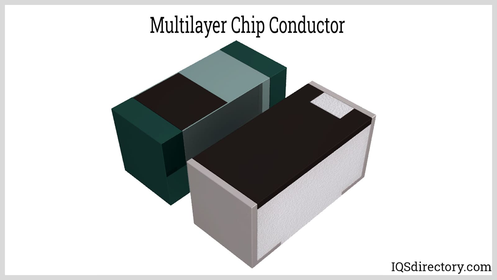
As indicated by the name, this inductor consists of multilayers. It is constructed by layering thin plates of ferrite material. The sheets are properly placed one layer after another, forming a coil and thus creating inductance. A special metallic paste is used to print the coil pattern on the layers.
Multilayer Chip Description
They have increased inductance and capacitance. Higher inductance results can be achieved at lower operating frequencies.
Multilayer Chip Applications and Features
- These inductors are used in small wearable applications
- They are used in wireless LANs
- Bluetooth
- SBCs
- Motherboard
- Their operating temperature range is -55°C to +125°C
- Thermal Shock ranges from -40°C to +85°C
Thin Film Inductor
The construction, description, and applications are detailed below.
Thin Film Construction
This type of inductor is made by using a substrate of very thin ferrite or any magnetic material. It is constructed by placing a spiral-shaped trace of conductive copper on top of the substrate.

Thin Film Inductor Description
The design of a thin film inductor provides resistance to vibrations and ensures stability.
Thin Film Inductor Applications and Features
- They’re utilized in mobile communication devices
- They are used in wireless networks
- They are used in power supply devices
Molded Inductor
The construction, description, and applications are detailed below.
Molded Inductor Construction
Just like resistors, this type of inductor is built by coating it with insulation such as molded plastic or ceramic material. The core material is either ferrite or phenolic. The winding is available in various designs and shapes, such as cylindrical, bar shapes, and axial forms.

Molded Inductor Description
They can achieve greater inductance levels and handle higher currents while maintaining a small volume, making them suitable for unobtrusive mounting in small, compact devices. These inductors enhance power optimization and reliability due to the stability of inductance across a wide current range, with only a gradual drop beyond rated currents.
Molded Inductor Applications and Features
- Molded inductors are used in SMD and THT also.
- They are used in PCB (Printed Circuit Boards), computers and mobile devices due to their lightweight and miniature size.
- They have high reliability and can achieve AEC-Q200 standard.
- Their frequency ranges up to 5MHz
- They exhibit less self-induced electromagnetic interference.
- High saturation current and DC bias
- Low profile or miniature size
Coupled Inductor
The construction, description, and applications are detailed below.
Coupled Construction
It is built by winding two lengths of wire around a common core. The windings can be connected in series, parallel, or configured as a transformer, depending on the application. These inductors operate based on the principle of mutual inductance, transferring energy from one winding to the other.

Coupled Inductor Description
They reduce inductor current ripple, maintain transient performance, and provide higher converter efficiency. Additionally, they experience relatively insignificant power loss due to current ripple.
Coupled Inductor Applications
- They are used in flyback converters
- Used in SEPIC converters
- Used in Cuk converters
Power Inductor
The construction, description, and applications are detailed below.
Power Construction
These inductors are designed to handle high currents without reaching magnetic saturation. To increase the saturation current rating, the inductor’s magnetic field is amplified. This increase in magnetic field can lead to EMI (electromagnetic interference). Most power inductors use proper shielding to mitigate EMI.

Power Inductor Description
Power inductors feature low resistance values, high current capability, low magnetic flux leakage, and high inductance values. They are lightweight and space-saving, with an optimized temperature range of up to +150°C.
Power Inductor Applications and Features
They are used to convert a certain voltage in a step-up or step-down circuit to the required voltage.
Chokes
Below are the details on the construction, description, and applications.
Chokes Construction
This type of inductor is very simple but is specifically designed to block (choke) high-frequency signals. As the frequency increases, the impedance of the choke rises significantly. Consequently, it allows low-frequency AC and DC to pass through while blocking high-frequency AC. Choke inductors are constructed without employing techniques for impedance reduction that are used to increase their Q-factor. Instead, chokes are intentionally designed to have a low Q-factor so that their impedance increases as the frequency rises.

Choke Description
Chokes allow low-frequency AC and DC to flow while blocking high-frequency AC. They have a low Q-factor, meaning their impedance increases as the frequency rises.
Choke Applications and Features
- The AF (Audio Frequency) chokes are used to block audio frequency and only allow DC.
- The RF (Radio Frequency) chokes are used to block RF frequency and only allow DC and audio frequency.
Color Ring Inductor
Detailed information on the construction, description, and applications is provided below.
Color Ring Inductor Construction
By wrapping a very thin copper wire around a dumbbell-shaped ferrite core and attaching two lids at the top and bottom of the core, a color ring inductor is created. The inductor is then molded with a green material coating. Values are indicated by colored bands printed on the coating. These colors can be read and compared with a color code chart, similar to how resistor values are determined.

Color Ring Inductor Description
These inductors feature a compact structure, being both small and lightweight. They are resistant to humidity due to their epoxy resin coating, which enhances their durability. They offer a high resonant frequency along with a high Q factor and are RoHS compliant.
Color Ring Applications and Features
- These inductors are used in line filters
- Boost converter
- Filter design
- Their operating temperature range is between -55°C and +105°C
- Storage temperature range is -55°C to +105°C
- Moisture sensitivity level -1
- Temperature rise -35°C
Shielded Surface Mount Inductor
Below are the details regarding the construction, description, and applications.
Shielded Surface Mount Construction
It is constructed by wrapping a length of wire in a cylindrical bobbin and enclosing it in a special housing form of ferrite, shielded surface mount inductor.

Shielded Surface Mount Inductor Description
The shielding minimizes EMI and noise from the inductor, enabling its use in high-density designs. These inductors are particularly suited for PCB-mounted applications.
Shielded Surface Mount Applications and Features
- These inductors are used in high current POL converters
- They are used in high current power supplies
- They are used in distributed power systems on DC/DC converters
- They are utilized in devices that are battery powered
- PDA or desktop or notebook or server applications
- They have shielded construction
- Their frequency ranges up to 5.0 MHz
- They can handle high transient current spikes without getting saturated
- Due to their composite construction, they exhibit ultra-low buzz noise
Wireless Charging Coils
The construction, description, and applications are detailed below.
Wireless Charging Coils Construction
These inductors are made by coiling a length of multi-stranded wire and then placing it in a ferrite material. The use of multi-stranded wire helps reduce the skin effect, enabling the generation of a high-frequency magnetic field that penetrates to a certain depth. If a solid wire were used, most of the current would flow through the outer part of the conductor, increasing resistance. The ferrite plate beneath the coil enhances the inductance, concentrates the magnetic field, and reduces emissions.

Wireless Charging Coil Description
They are efficient in charging, reliable, and cost-effective, offering reduced thickness for various applications. They feature low thermal loading and low DC resistance, ensuring high efficiency.
Wireless Charging Coils Applications and Features
- These inductors are used in wireless charging
- They are used in information and communication devices
- They are used in medical, industrial and other devices
- Example features
- Rdc (Ohm) : 0.08Ω
- Rs (Ohm) : 0.095Ω +/-10%@100kHz
- Ls (uH) : 6.20uH +/-5%@100kHz
Shielded Variable Inductor
The construction, description, and applications are detailed below.
Shielded Variable Inductor Construction
This type of inductor is constructed by winding a length of wire around a hollow cylindrical bobbin. The inductance value can be adjusted by positioning and moving a ferromagnetic or brass core. When using a ferrite core, the inductance increases as the core is moved towards the center of the winding. Conversely, with a brass core, the inductance decreases as the core is moved to the center of the winding.

Shielded Variable Inductor Description
The inductance can be adjusted by altering the position of the core, making it suitable for highly sensitive applications where a fixed inductor might not offer precise alignment.
Shielded Variable Inductor Applications
- These inductors are used in automotive applications
- AEC-Q200 complaint
- Frequency ranges from 20 to 129 MHz
- Inductance ranges from 0.05 to 2.7 MH
- They are highly durable when it comes to mechanical stress
Chapter 5: What Is Inductance and What Factors Affect the Inductance of an Inductor Coil?
This chapter will cover the inductance of an inductor coil and the factors that influence it.
The concept of inductance in an inductor coil will be explained in detail below.
Inductance of an Inductor Coil
The concept of inductance in an inductor coil will be discussed below.
Inductance Characteristics
Inductance is a property of an electrical circuit that resists changes in current. This resistance is caused by the creation or destruction of a magnetic field. When current starts to flow, it generates magnetic field lines of force. These lines induce a counter electromotive force (emf) that opposes the current by interacting with the conductor. In other words, inductance is the phenomenon in which a changing magnetic field affects the flow of electricity within the circuit.
Self-Inductance Process
Self-inductance refers to the process where a circuit uses its own changing magnetic field to induce an emf within itself. This property is inherent in all electrical circuits. Self-inductance only manifests when there is a change in the electric current, opposing only changes in current rather than the current itself.

Mutual-Inductance Process
Two coils exhibit mutual inductance when the magnetic flux from one coil intersects the turns of the other coil. The extent of mutual inductance is influenced by several factors, including:
- The position of the axes of the two coils relative to one another.
- The permeability of the cores, the physical dimensions of the two coils.
- The distance between the coils and the number of turns or wraps in each coil.
The degree of coupling between the coils is defined by the coefficient of coupling \( K \). The coefficient of coupling \( K \) is equal to 1 (or unity) if all the magnetic flux from one coil intersects all the turns of the other coil. Conversely, if none of the flux from one coil intersects the turns of the other coil, the coefficient of coupling is zero.

Factors Affecting Coil Inductance
Several factors can influence coil inductance, including:
Number of Turns/Wraps in the Coil
Increasing the number of turns in a coil enhances its inductance, assuming all other factors remain constant. Conversely, fewer turns result in lower inductance. This is because additional turns generate a stronger magnetic field (measured in amp-turns) for the same amount of current, thereby increasing the coil's inductance.

Coil Area
Assuming all other factors are equal, a larger coil area results in higher inductance. Conversely, a smaller coil area leads to lower inductance. This is because a larger coil area offers less resistance to the formation of magnetic flux for a given field force (amp-turns), thereby increasing the inductance.

Coil Length
All other factors being equal, a longer coil length results in lower inductance, while a shorter coil length provides higher inductance. This is because a longer coil length increases the path that the magnetic field flux must travel, leading to greater opposition to the formation of the flux for any given field force.

Core Material
Assuming all other factors are equal, a core material with higher magnetic permeability will result in greater inductance. Conversely, a core with lower permeability will produce less inductance. This is because materials with higher magnetic permeability generate a stronger magnetic field flux for a given magnitude of field force (amp-turns).

Chapter 6: What Considerations Should Be Taken into Account When Choosing an Inductor Coil?
When selecting inductor coils, several factors need to be considered:
Circuit Requirements and Inductor Performance
When reviewing application requirements, an engineer must select the appropriate type of inductor. The chosen inductor should meet circuit specifications and enhance performance. Many inductors are crucial for power circuits or for blocking radio frequency interference.
Power Circuit Applications
In power circuit applications, both incremental and maximum currents must be considered. Incremental current refers to the current level at which inductance starts to decrease, while maximum current pertains to the current level that exceeds the temperature rating of the application device.
RF Considerations
When choosing an inductor for an RF application, two factors must be kept in mind:
- Q factor (quality), which is related to the resistance value of the inductor. An ideal value is the high Q factor.
- Self-Resonant Frequency (SRF), which is the frequency when the device stops its role as an inductor. A minimum SRF value must always be selected.
Inductor Size and Shielding
The size of the inductor is determined by the application. For instance, power circuits necessitate large inductors, whereas RF applications typically use small ferrite core inductors. Additionally, compatibility with filter capacitors is crucial for larger inductors. RF devices usually have lower power requirements. To minimize magnetic coupling between components, all inductors should be shielded.
Tolerance Percentage
The tolerance percentage should be compared with the device's inductive value by reviewing the manufacturer's datasheet. Before purchasing an inductor, it is essential to check the datasheet to ensure that the specifications align with the application requirements.
Conclusion
There are many different types of inductor coils with different characteristics as a result of their core material, shape, or use. All these inductors have different properties and functions; therefore, one must be aware of these properties and functions in order to choose the right inductor for a certain application. The factors affecting inductance must also be taken into consideration.