






Bevel Gears: Types, Processes and Applications
IQS Directory EditorialUpdated 6 chapters
7 leading suppliers listed with this guide
Browse bevel gear suppliersContents (6 chapters)
This article provides a comprehensive look at bevel gears, include the following information:
- What is a Bevel Gear?
- Efficiency of Bevel Gears
- Bevel Gear Types
- Geometry and Terminologies
- Manufacturing Processes
- Applications of Bevel Gears
- And much more…
Chapter 1: Understanding Bevel Gears
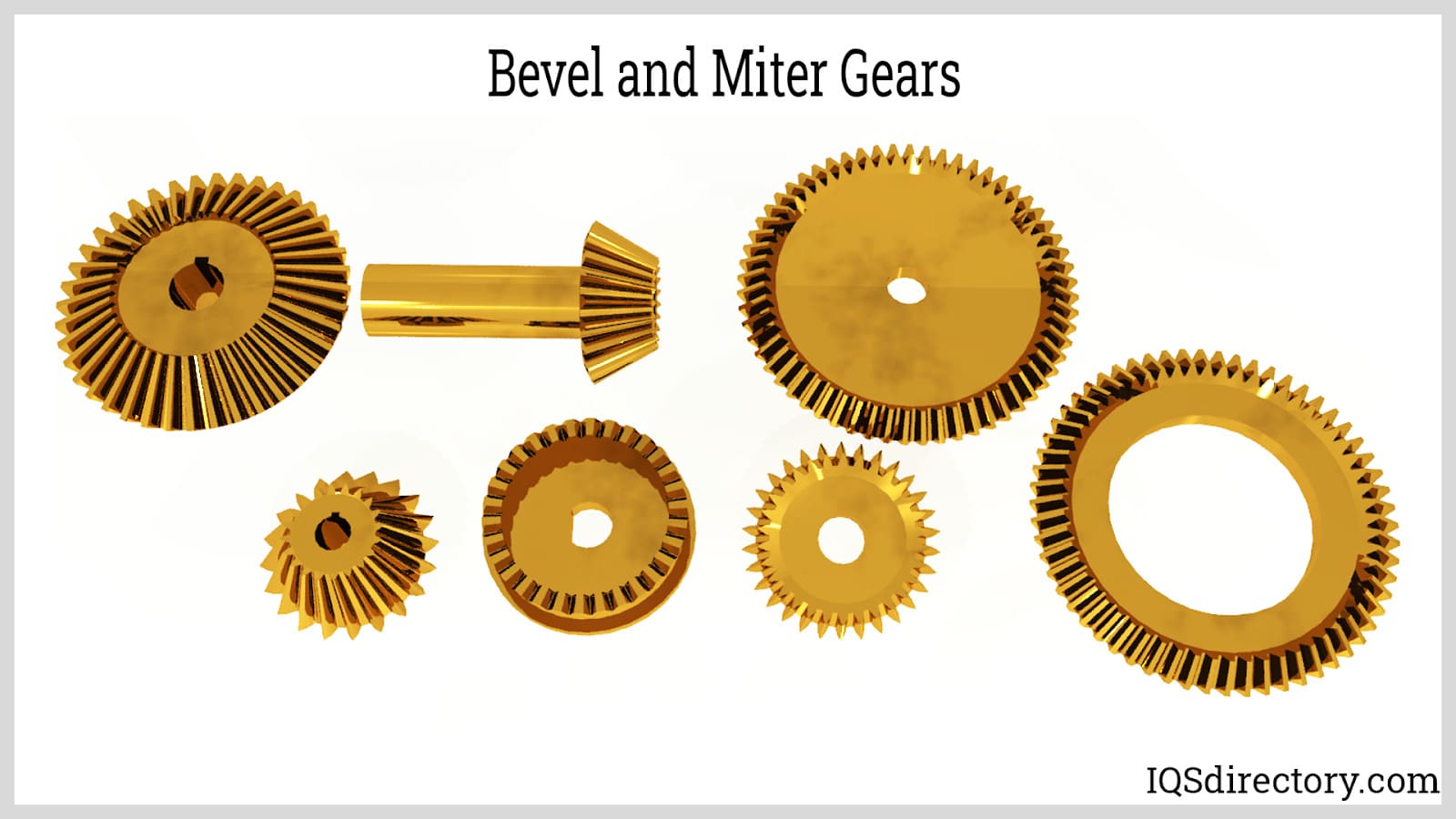
Bevel gears are toothed, rotating mechanical components designed to transmit power and mechanical energy between intersecting shafts, most commonly at a 90-degree angle. In applications where a change in shaft direction is required, bevel gear sets provide efficient torque transmission while adjusting rotational speed and output torque. Because of this, they are widely used in power transmission systems, right-angle drives, differential gear assemblies, industrial machinery, automotive differentials, and other motion control applications where reliable speed reduction or speed increase is needed.
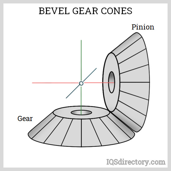
Structurally, a bevel gear is similar to a truncated cone, with teeth cut along its sloped surface to mesh with another gear in a gear train. The gear supplying power to the shaft is called the driver gear, while the gear receiving that power is the driven gear. In most bevel gear configurations, the driver and driven gears have different tooth counts to create a mechanical advantage and achieve the desired gear ratio. The gear ratio is calculated by comparing the number of teeth on the driven gear to the number of teeth on the driver gear, and this relationship directly affects torque multiplication, speed reduction, and overall efficiency. This relationship is illustrated by the following formula:
The mechanical advantage (MA) depends on several key parameters, including the torques (τb and τa), pitch radii (rb and ra), and tooth counts (Nb and Na) of the driven and driver gears. In practical terms, a bevel gear with more teeth on the driven side increases output torque, making it ideal for applications that require heavy-load performance, controlled motion, and dependable power transfer.
In contrast, an increase in mechanical advantage typically results in a reduction in the driven gear's output speed. This speed-torque tradeoff is central to bevel gear performance and is especially important when selecting gears for precision machinery, gearboxes, and drivetrain systems. The relationship is articulated by this equation:
ωa and ωb represent the angular speeds of the driver and driven gears, respectively. Typically, a 10:1 gear ratio is ideal for a bevel gear set, whereas a 1:5 ratio is advised for elevating the driven gears' speed. When evaluating bevel gear types, buyers also consider load capacity, backlash, noise levels, wear resistance, material selection, and lubrication requirements, since these factors influence durability, operating smoothness, and long-term maintenance costs.
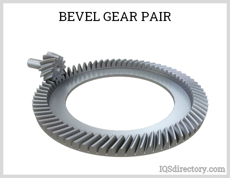
It is important to remember that bevel gears come as matched pairs and should not be interchanged. Bevel gears are precisely assembled to handle transmission of both thrust and radial loads, differentiating them from spur gears, which primarily manage radial loads. The assembly of all bevel gears is performed at an optimal position to ensure peak performance, proper tooth contact, and efficient power transmission. For engineers and procurement teams comparing bevel gear suppliers, common selection criteria include gear type, mounting orientation, operating environment, and custom manufacturing capabilities.
Chapter 2: How Efficient Are Bevel Gears?
Efficiency, a core consideration in mechanical power transmission, is defined as the ratio of output power to input power in a given system. Unlike mechanical advantage—which centers on amplifying forces or torque with a trade-off in speed—efficiency directly measures how effectively power is transferred from a driving gear to a driven gear, minimizing energy losses. In bevel gear systems, power loss primarily stems from friction between meshing gear teeth, sliding action, and forces exerted on bearings or the gear housing. Proper lubrication and precision engineering are crucial for reducing these losses, thereby increasing the operational efficiency and lifespan of your gear assemblies. Understanding gear efficiency is vital when selecting the right gear type for applications in automotive, industrial machinery, robotics, and heavy equipment, where performance, reliability, and energy savings are paramount.
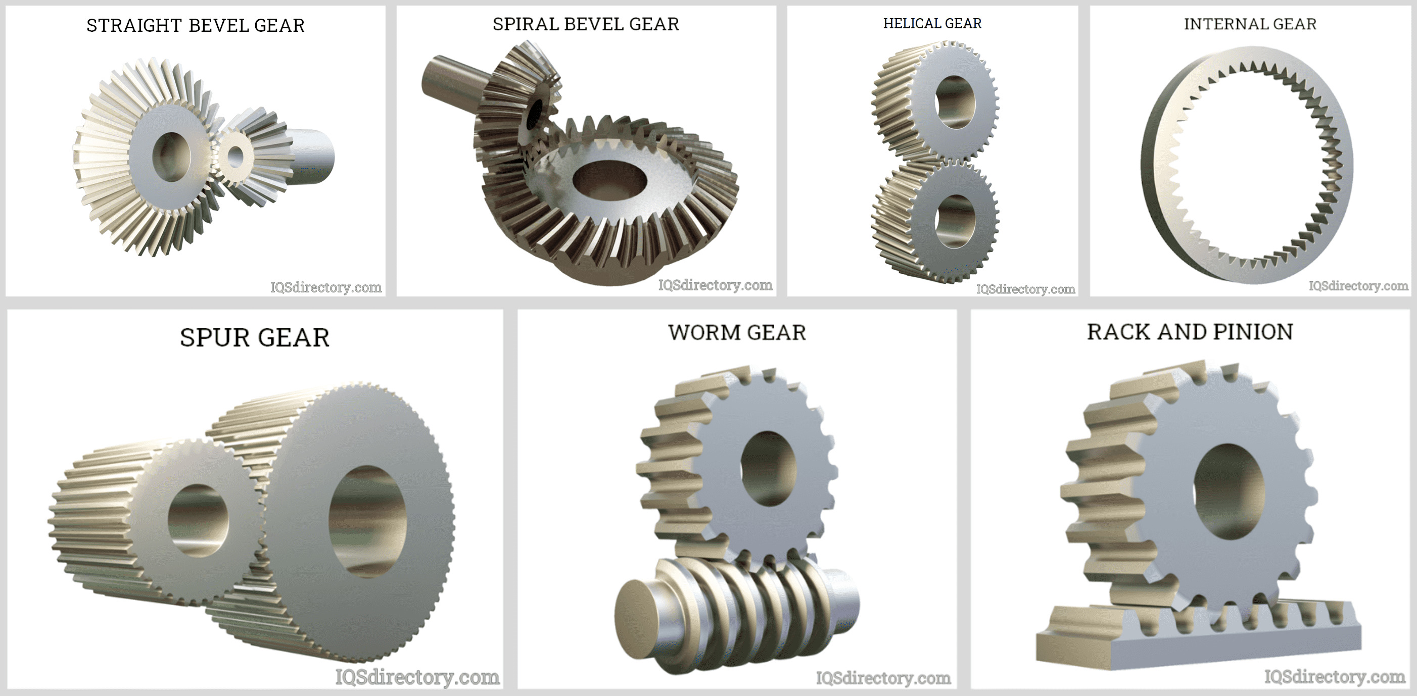
Bevel gears, including straight bevel gears, spiral bevel gears, zerol bevel gears, and hypoid gears, are widely used to change the direction of shaft rotation and transmit power between intersecting axes. The efficiency of bevel gears varies based on their geometry, application, load carrying capacity, and alignment precision. The following table compares the efficiency ranges and bearing loads of common gear types, highlighting how bevel gears typically outperform other right-angle drives such as worm gears.
| Type of Gear | Approximate Range of Efficiency | Type of Load Imposed in Bearings |
|---|---|---|
| Straight Bevel Gear | 97 – 99.5% | Radial and thrust |
| Spiral Bevel Gear | 97 – 99.5% | Radial and thrust |
| Zerol Bevel Gear | 97 – 99.5% | Radial and thrust |
| Hypoid Bevel Gear | 90 – 98% | Radial and thrust |
| External Spur Gears | 97 – 99.5% | Radial |
| Internal Gears | 97 – 99.5% | Radial |
| Worm Gear | 50 – 90% | Radial and thrust |
Factors Affecting Bevel Gear Efficiency
Several elements influence the efficiency of bevel gears, including:
- Tooth geometry and surface finish: High-precision, accurately machined teeth reduce frictional losses and allow optimal meshing, lowering heat generation.
- Quality of lubrication: Using specialty gear oil or synthetic lubricants minimizes wear, reduces sliding friction, and sustains higher efficiency over prolonged operation.
- Alignment and installation: Misaligned shafts or improper assembly can increase load on bearings and gear teeth, reducing overall efficiency and causing premature failure.
- Speed and load: Operating at excessively high speeds or under heavy loads can accelerate wear, increase friction, and slightly decrease efficiency compared to running under nominal recommendations.
For optimal performance, bevel gear selection should consider not only efficiency ratings but also maximum torque, gear ratio, noise levels, backlash tolerance, and suitability for the intended application—whether in differential drives, conveyors, or precision instrumentation. Consulting with a leading bevel gear manufacturer or specialized supplier can help identify the right gear type, material (such as alloy steel or hardened cast iron), and customization options to meet unique system requirements.
Looking to purchase high-efficiency bevel gears? OEMs and maintenance engineers frequently compare suppliers based on gear quality, manufacturing certifications (such as ISO 9001), customization capabilities, lead time, and after-sales support. Use the list below of industry-leading manufacturers to help streamline the sourcing process and ensure long-term reliability for your power transmission systems.
Chapter 3: What Are the Different Types of Bevel Gears?
Bevel gears are a fundamental component in mechanical power transmission, renowned for their capability to transfer motion between intersecting shafts, typically at right angles. They come in various types, classified by tooth profile, geometry, and orientation—attributes that significantly influence their application in industrial machinery, automotive systems, and precision equipment. Advancements in gear manufacturing, such as CNC machining, gear hobbing, and precision grinding, have enabled the production of increasingly complex forms, including spiral, Zerol, and hypoid bevel gears with superior performance characteristics.

Straight Bevel Gears
The straight bevel gear is the most traditional and straightforward type of bevel gear, featuring teeth that are cut straight and extend toward the apex of the gear cone. These gears have tapered teeth, with the outer section (heel) wider than the inner part (toe), and the lines of contact are instantaneous. This arrangement creates simplicity in assembly and greater mounting tolerance. Although straight bevel gears are valued for their ease of manufacture and cost-effectiveness, they tend to produce higher vibration and noise—characteristics that limit their use to low-speed or static load applications, such as the differential systems in automobiles and manual machinery.
Manufacturing straight bevel gears typically involves processes such as gear planing with an indexing head, but innovations like the Revacycle and Coniflex systems from Gleason Works have increased production efficiency, accuracy, and cost competitiveness. These gears are frequently found in agricultural equipment, industrial gearboxes, and railway track inspection vehicles, where moderate load handling and straightforward power transmission are prioritized over quiet operation.

Spiral Bevel Gears
Spiral bevel gears represent a significant advancement in bevel gear technology. Their teeth are curved and obliquely oriented, unlike the linear teeth of straight bevel gears. This spiral tooth design allows for greater contact ratio and gradual engagement, which leads to smoother, quieter, and more efficient power transmission. Due to higher load capacity and reduced vibration, spiral bevel gears are ideal for high-speed, heavy-duty applications such as automotive rear axles, industrial drives, helicopter transmissions, and precision robotics.
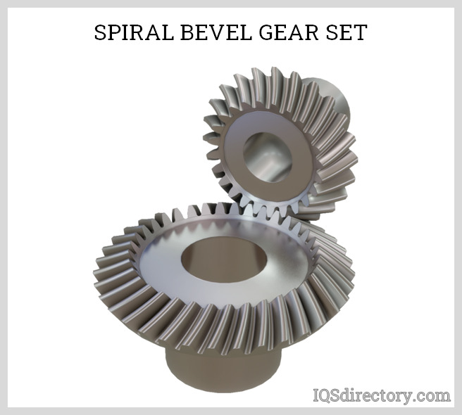
One trade-off of spiral bevel gears is the increased thrust load generated, necessitating robust rolling element thrust bearings for proper support. Spiral bevel gears are usually manufactured and paired as matched sets, ensuring optimized meshing and precise backlash settings; replacement without specific matching can lead to failure. Manufacturing involves specialized gear generating machines — a process resulting in excellent accuracy and finish. Post-machining processes such as lapping or grinding further refine tooth surface quality and operational smoothness, extending service life in demanding environments.
Zerol Bevel Gears
Zerol bevel gears offer a unique blend of design features found in both straight and spiral bevel gears. Originally developed by Gleason Works, these gears have teeth that are curved along their length but feature a 0° spiral angle, setting them apart from conventional spiral bevel gears, which typically exhibit a 35° spiral angle. As a result, Zerol bevel gears provide a moderate amount of tooth overlap, improving smoothness while minimizing the thrust loads seen in spiral designs.

Zerol bevel gears are commonly used in industrial power transmission, precision motion devices, and applications where quiet operation and high assembly flexibility are desired. They permit the use of simpler plain contact bearings and can often replace straight bevel gears without major design modifications. Manufacturing is accomplished using rotary mill cutters, imparting a curved profile that delivers enhanced lubrication retention, reduced stress concentration, and improved durability. Finishing processes include lapping and grinding to achieve tight tolerances and a fine surface finish, essential for high-precision or high-speed uses.
Hypoid Bevel Gears
Hypoid bevel gears provide a sophisticated solution for transmitting power between non-intersecting, right-angle shafts. Unlike standard bevel gears, the axes of hypoid gears do not intersect, resulting in an "offset" that allows for larger diameter pinions, increased gear ratio choices, and elevated torque transmission. These factors make hypoid gears the preferred choice in automotive rear axles (e.g., truck differentials), heavy machinery drives, and high-performance industrial equipment where greater strength and compact installation are required.
The spiral angle of the hypoid pinion is typically greater than that of the mating gear, further increasing the number of teeth in mesh and reducing noise, vibration, and harshness (NVH). However, the significant sliding action across the hypoid tooth face introduces higher friction and heat generation, demanding the use of specialized extreme-pressure (EP) lubricants. Application-specific considerations—such as bearing selection, housing rigidity, and careful gear alignment—are critical for maximizing efficiency and service life. Excessive offset, while beneficial for design flexibility, may reduce gear train efficiency.

To ensure optimal performance and longevity, manufacturers employ advanced gear cutting and shaping methodologies, similar to those for spiral bevel gears. When considering hypoid bevel gears for your application, it is essential to evaluate lubrication requirements, potential for thermal expansion, and load-carrying capabilities.
Miter Bevel Gears
Miter gears are a specialized class of bevel gears uniquely characterized by their 1:1 gear ratio—meaning the driving and driven gears have the same number of teeth. Unlike other gear types, miter gears do not alter torque but are commonly used to change the direction of rotational motion, making them invaluable for transmission systems where input and output shafts need to be oriented at various angles. The most frequent shaft arrangement is at 90° (perpendicular), but variants can be engineered for intersecting angles between 45° and 120°—a configuration known as angular miter bevel gears.
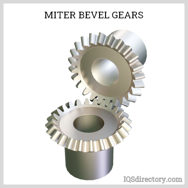
Miter bevel gears are produced in several tooth forms—straight, spiral, or Zerol—each offering different advantages depending on application requirements. Industries such as robotics, conveyor systems, printing presses, and machine tools frequently choose miter gears for their efficiency in transmitting power and reliability over long operational cycles. Proper selection entails evaluating factors such as tooth geometry, mounting arrangements, material selection, load requirements, and operational speed.
When specifying or sourcing bevel gears—whether straight, spiral, Zerol, hypoid, or miter—it is crucial to align gear type selection with your application's design requirements, torque needs, noise tolerance, lubrication preferences, and installation constraints. Working with experienced gear manufacturers can help optimize not only transmission efficiency but also system longevity and operational reliability.
Frequently Asked Questions
What Is a Bevel Gear and How Does It Function?
A bevel gear is a truncated cone-shaped gear with sloped teeth, designed to transmit power between intersecting shafts at changing angles, commonly at 90 degrees. It adjusts torque and speed based on its gear ratio, offering mechanical advantage in various applications.
How Efficient Are Bevel Gears Compared to Other Gear Types?
Bevel gears, such as straight, spiral, and Zerol types, typically offer efficiency rates between 97% and 99.5%. This outperforms worm gears, which can have efficiencies as low as 50%. Efficiency depends on factors like tooth geometry and lubrication quality.
What Factors Influence the Efficiency of Bevel Gears?
Bevel gear efficiency is affected by precision of tooth geometry, surface finish, lubrication quality, alignment during installation, operating speed, and load conditions. Proper assembly and lubrication significantly reduce friction, heat, and wear, ensuring optimum performance and longevity.
What Are the Main Types of Bevel Gears and Their Uses?
The primary bevel gear types are straight, spiral, Zerol, hypoid, and miter. Straight bevel gears suit low-speed or static loads; spiral and hypoid excel in high-speed or heavy-duty applications; Zerol balances smoothness and low thrust; miter gears are used for changing shaft orientation.
Why Is It Important to Use Matched Pairs of Bevel Gears?
Bevel gears must be used in matched pairs to ensure precise assembly and optimal meshing. Using unmatched gears can cause improper load distribution, increased wear, noise, and risk of failure due to incorrect alignment or backlash.
How Do Bevel Gears Support Industrial Applications in the United States?
Bevel gears are widely used in U.S. industries including automotive, industrial machinery, robotics, and heavy equipment, supporting efficient power transmission, torque adjustment, and directional change between intersecting shafts in demanding environments.
Chapter 4: What Are the Basic Geometries and Terms for Bevel Gears?
To gain a clearer understanding of gears and gear systems, it's essential to familiarize oneself with key terminology. The terms listed below describe various aspects of gears and their tooth profiles and are applicable to all types of gears, not just bevel gears.

Pinion
The smaller gear in a bevel gear set that drives the larger gear.
Gear
The larger gear in a bevel gear set that is driven by the smaller pinion gear.
Pitch
Also known as circular pitch, this is the distance between corresponding points on adjacent teeth of the same gear.
Pitch Diameter
The diameter of the pitch circle, which is a critical design parameter for determining tooth thickness, pressure angles, and helix angles of the gear.
Diametral Pitch
The ratio of the number of teeth to the pitch diameter of a gear.
Pitch Angle
The angle between the face of the pitch surface and the axis of the shaft.

Pitch Surface
The imaginary truncated cone where the base diameter corresponds to the pitch circle.
Pressure Angle
The angle between the line of force of the meshing teeth and the tangent to the pitch circle at the contact point. For proper meshing, gears must have the same pressure angle. The recommended pressure angle for straight bevel gears is 20°.
Shaft Angle
The angle between the shafts of the driver and driven gears.
Addendum
The upper outline of the gear teeth, extending from the pitch circle to the top of the teeth.
Dedendum
The lower outline of the gear teeth, extending from the pitch circle to the bottom of the teeth.
Total Depth
The radial distance between the addendum and dedendum circles. Due to the slight taper of bevel gear teeth, this depth is not constant along the tooth. Addendum and dedendum angles are used to describe the teeth more accurately than the circles.
Addendum Angle
The angle between the top surface of the teeth (top land) and the pitch surface.
Dedendum Angle
The angle between the bottom surface of the teeth (bottom land) and the pitch surface.
Depth of Taper
The variation in tooth depth along the face, measured perpendicular to the pitch surface.
Space Width Taper
The variation in space width along the face, measured on the pitch surface.
Thickness Taper
The variation in tooth thickness measured on the pitch surface.
Working Depth
The total depth of the teeth plus the clearance value.
Clearance
The difference between the addendum of one gear and the dedendum of the mating gear.
Backlash
The space between the mating gear teeth that exceeds their thickness. Different types of backlash are defined based on movement orientation:
Circular
The arc along the pitch circle.
Normal
The space between the surfaces of mating teeth.
Angular
The angular movement described by the backlash.
Radial
The linear movement perpendicular to the axis.
Axial
The linear movement parallel to the axis.
Backlash is crucial for preventing gear jamming due to contact. It allows lubricants to enter and protect the mating teeth surfaces and accommodates thermal expansion during operation.
The relationship between these terms is illustrated in the table of equations below.
| To Find | Having | Formula |
|---|---|---|
| Pitch diameter of pinion | Number of pinion teeth and diametral pitch | d = Np / Pd |
| Pitch diameter of gear | Number of gear teeth and diametral pitch | D = Ng / Pd |
| Pitch angle of pinion | Number of pinion teeth and number of gear teeth | γ = tan^-1(Np / Ng) |
| Pitch angle of gear | Pitch angle of pinion | Γ= 90°-γ |
| Outer cone distance of pinion and gear | Gear pitch diameter and pitch angle of gear | Ao = D / (2sinΓ) |
| Circular pitch of pinion and gear | Diametral pitch | p = 3.1416 / Pd |
| Dedendum angle of pinion | Dedendum of pinion and outer cone distance | δp = tan-1(bop / Ao) |
| Dedendum angle of gear | Dedendum of gear and outer cone distance | δg = tan-1(bog / Ao) |
| Face angle of pinion blank | Pinion pitch angle and dedendum angle of gear | γo = γ + δg |
| Face angle of gear blank | Gear pitch angle and dedendum angle of pinion | Γo = Γ + δp |
| Root angle of pinion | Pitch angle of pinion and dedendum angle of pinion | γr = γ - δp |
| Root angle of gear | Pitch angle of gear and dedendum angle of gear | Γr = Γ - δg |
| Outside diameter of pinion | Pinion pitch diameter of gear, pinion addendum, and pitch angle of pinion | do = d +2aop cosγ |
| Outside diameter of gear | Pitch diameter of gear, gear addendum, and pitch angle of gear | Do = D + 2aog cosΓ |
| Pitch apex to crown of pinion | Pitch diameter of gear, addendum, and pitch angle of pinion | xo = (D/2) - aop sinγ |
| Pitch apex to crown of gear | Pitch diameter of pinion, addendum, and pitch angle of gear | Xo = (d/2) - aog sinΓ |
| Circular tooth thickness of pinion | Circular pitch and gear circular tooth thickness | t = p - T |
| Chordal thickness of pinion | Circular tooth thickness, pitch diameter of pinion and backlash | tc = t - (t3/6d2) - (B/2) |
| Chordal thickness of gear | Circular tooth thickness, pitch diameter of gear and backlash | Tc = T - (T3/6D2) - (B/2) |
| Chordal addendum of pinion | Addendum angle, circular tooth thickness, pitch diameter, and pitch angle of pinion | acp=aop + (t2 cosγ / 4d) |
| Chordal addendum of gear | Addendum angle, circular tooth thickness, pitch diameter, and pitch angle of gear | acg=aog + (T2 cosΓ / 4D) |
| Tooth angle of pinion | Outer cone distance, tooth thickness, dedendum of pinion, and pressure angle |
(3.438/Ao)(t/2)+bop tanφ
min |
| Tooth angle of gear | Outer cone distance, tooth thickness, dedendum of gear, and pressure angle |
(3.438/Ao)(T/2)+bog tanφ
min |
| To Find | Having | Formula |
|---|---|---|
| Pitch diameter of pinion | Number of pinion teeth and diametral pitch | d = Np / Pd |
| Pitch diameter of gear | Number of gear teeth and diametral pitch | D = Ng / Pd |
| Pitch angle of pinion | Number of pinion teeth and number of gear teeth | γ = tan-1(Np / Ng) |
| Pitch angle of gear | Pitch angle of pinion | Γ= 90°-γ |
| Outer cone distance of pinion and gear | Pitch diameter of gear and pitch angle of gear | Ao = D / (2sinΓ) |
| Circular pitch of pinion and gear | Diametral pitch | p = 3.1416 / Pd |
| Dedendum angle of pinion | Dedendum of pinion and outer cone distance | δp = tan-1(bop / Ao) |
| Dedendum angle of gear | Dedendum of gear and outer cone distance | δg = tan-1(bog / Ao) |
| Face angle of pinion blank | Pitch angle of pinion dedendum angle of gear | γo = γ + δg |
| Face angle of gear blank | Pitch angle of gear and dedendum angle of pinion | Γo = Γ + δp |
| Root angle of pinion | Pitch angle of pinion and dedendum angle pinion | γr = γ - δp |
| Root angle of gear | Pitch angle of gear and dedendum angle of gear | Γr = Γ - δg |
| Outside diameter of pinion | Pitch diameter, addendum, and pitch angle of pinion | do = d +2aop cosγ |
| Outside diameter of gear | Pitch diameter, addendum, and pitch angle of gear | Do = D + 2aog cosΓ |
| Pitch apex to crown of pinion | Pitch diameter of gear, pitch angle, and addendum of pinion | xo = (D/2) - aop sinγ |
| Pitch apex to crown of gear | Pitch diameter of gear, pitch angle, and addendum of gear | Xo = (d/2) - aog sinΓ |
| Circular tooth thickness of pinion | Circular pitch of pinion and circular pitch of gear | t = p - T |
Chapter 5: What Are the Common Manufacturing Processes?
There are four main methods of manufacturing gears. These are metal cutting, casting, forming, and powder metallurgy. Metal cutting is the most widely used process because of its dimensional accuracy. The second two, casting and forming, are used in special circumstances- for example, producing a large gear through casting, which reduces machining expenses by casting closer to the final shape. Another form of casting, known as injection molding, is used to manufacture plastic gears. Forming, on the other hand, can take the form of cold drawing or forging. Cold drawing involves a stock pulled or extruded into a series of dies to form the shape of the gear. Forging presses the stock against dies with the desired tooth configuration. Because of work hardening through continuous deformation, the resulting gear is harder, with a more contoured grain flow.

Gear cutting can be categorized into four distinct methods, summarized as follows:
- Rotating threaded tool: hobbing, generating
- Rotating and reciprocating tool: shaping, shaving, generating
- Rotating disc wheel: milling, form grinding, thread grinding
- Linear motion tool: broaching, punching

Due to the conical shape of bevel gears, which introduces both depth and width taper, not all cutting techniques are applicable. For bevel gear cutting, metal cutting methods are generally classified into two categories: face hobbing and face milling.
-
Face Hobbing: Face hobbing is a continuous indexing gear generation process. This involves groups of cutting blades that cut all teeth gradually until the desired depth is achieved. As one blade group cuts one tooth, the next blade group enters the next tooth space. The cutting tool and the workpiece rotate simultaneously.

-
Face Milling: Face milling is a single indexing method where the cutting wheel or tool is fed to cut one tooth space and is then indexed to the next tooth location. The cutting tool and the workpiece are synched together to perform the cut. Each tooth is milled until all teeth are cut to the required depth. Face milling can be done by a two-tool planer, double rotary blade, single row mill cutter, or five-axis CNC milling machines.

- Powder Metallurgy: Powder metallurgy is a process in which metal powders are formed into products or materials. In its most basic form, this is achieved by pulverizing the desired material into a powder, compacting the powder into a die, and then sintering. This manufacturing process is valued due to the fact that metal removal processes are often not needed for secondary finishing, which results in less waste and, therefore lower costs. Gears that are formed by this process are lighter and make less noise, due to their naturally porous nature.
Chapter 6: What Are Some Applications of Bevel Gears?
Bevel gears offer a straightforward and effective solution for altering the axis of rotation in drivetrains. The choice of bevel gear type, as well as the manufacturing and finishing techniques, depends on the specific application. Below are some common applications of bevel gear systems.
Bevel Gears in Automotives
The most popular application of bevel gears is in the differential of an automotive vehicle. The differential is the part of the front or rear axle assembly that allows the wheels to rotate at different speeds. This allows the vehicle to turn corners while maintaining handling and traction. The driveshaft is connected to the hypoid gear assembly, which consists of a pinion and a ring gear. The ring gear is mounted to the carrier with other bevel gears in a planetary gear train.

Bevel Gears in Heavy Equipment
Bevel gears are utilized in heavy machinery for both propulsion, similar to an automotive differential system, and for driving auxiliary units.

Bevel Gears in Aviation
In the aviation industry, bevel gears are employed in power transmission systems for helicopters and aircraft accessory gearboxes.
Bevel Gears in Industrial Plant Equipment
An example of industrial plant equipment that uses bevel gears is cooling tower fans. The motor is usually mounted at the deck of the cooling tower with the shaft axis oriented horizontally. A gearbox assembly reduces the speed and increases the torque while also reorienting the axis of rotation vertically.

Bevel Gears in Marine Transmission
In marine transmissions, bevel gears are frequently utilized as part of the stern drive system. Typically, two bevel gear sets are employed between the engine and the propeller.

Bevel Gears in Hand Tools
- Drills - The use of bevel gears in drills is one of their most common uses. As the handle of the drill turns vertically, the bevel gear changes the direction to horizontal at the chuck. Additionally, bevel gears are used to control the rotation speed, making it possible to drill several types of material.
- Planers - Planers are used to shape a workpiece using linear motion. Bevel gears in planers allow for adjustments during the planing process and displacement caused by deflection.

Conclusion
- Bevel gears are rotating machine elements used to transmit mechanical power between two intersecting shafts, either perpendicular or at an angle. Aside from changing the axis of rotation, bevel gears can also produce a mechanical advantage by increasing the output torque.
- Producing a mechanical advantage, however, decreases the angular speed of the driven shaft. Thus, bevel gears can also be used as speed reduction mechanisms.
- Efficiency is the ratio between output power and input power. Power loss from bevel gears is mostly due to friction from sliding contact. This is then dissipated as heat, which is usually removed by lubricating oils.
- Bevel gears are classified according to the tooth profile and orientation. The types of bevel gears are straight, spiral, Zerol, and hypoid.
- Efficiencies of bevel gears range from 97-99.5%, except for hypoid bevel gears- with an efficiency of 90-98%. A larger offset of a hypoid gear causes a further decrease in efficiency.
- There are many terms used to describe gears. The most important for bevel gears are the pitch diameter, pressure angle, shaft angle, and number of teeth. These are the key values that will define the geometry of the gear.
- There are three main methods of manufacturing gears: cutting, casting, and forming. Among the three, cutting is the most widely used. Powder metallurgy is also used.
- Gear cutting is further broken down into several methods. One is by using a rotating threaded tool such as a hob. Next is by using a rotating or reciprocating cutting tool that mates together with the gear blank. Third is cutting using a rotating disc wheel as seen in milling processes. Lastly is gear cutting using a linear shaper or broaching tool.
- The most popular application of bevel gears is the automotive differential. This is seen not only in automotive vehicles, but also in light and heavy equipment. Other main uses are in the aviation and marine industries.